The primary objective in the thermal design of heat exchangers is to determine the necessary surface area required to transfer heat at a given rate for given fluid temperatures and flow rates. Although the necessary equations for heat transfer and the pressure drop in a double pipe heat exchanger are available using these equations the optimization of the system cost is laborious.

Calculating Fluid Contact Area And Tube Length For Counter Flow Heat Exchangers Youtube
Use two different methods Report the.

. Optimal design of the exchanger has been formulated as a. The double pipe heat exchanger has a small pipe that is surrounded by another large pipe. And ρp the mass density of the inner fluid.
Flow steam through outer pipe of double-pipe heat exchanger Allow to come to steady stat e monitor. Specifically in this case we will limit ourselves to the case when the overall heat transfer coefficient is constant and the other. Determination of the heat transfer surface area needed for a double pipe heat exchanger design can be done using the basic heat exchanger equation.
940 M ˆ i h i M ˆ o h o Q ˆ 0. This equation must be discretised along the heat exchanger into a suitable number of sections. The inner wall of the small pipe is the heat transfer surface.
Q is the rate of heat transfer between the two fluids in the heat exchanger in Btuhr U is the overall heat transfer coefficient in BTUhr-ft2-oF. DoublePipe Heat exchanger counter current cold less cold less hot hot. In this paper the.
They are easy to repair and due to the straightforward design they are used widely in many applications and are the first choice for a. If the thermal service demands a higherheattransferareaseveralhairpinscanbeinterconnected. It is one heat.
The basic heat exchanger equations applicable to shell and tube exchangers were developed in Chapter 1. A double-pipe heat transfer exchanger consists of one or more pipes placed concentrically inside another pipe of a larger diameter with appropriate fittings to direct the flow from one section to the next. The heat transfer efficiency between the fluids varies along the heat exchanger as among other reasons the thermal properties change with temperature and complex thermal phenomena take place inside the heat exchanger.
Geometric programming with a single degree of difficulty. Let us first consider the equations for double-pipe or shell-and-tube heat exchangers. 25 The total heat transfer to the wall all along the pipe is 18.
Hairpin Heat exchangers with Multitube Finned inner Tubes From Equations 74 75 78 79 and 710 the hydraulic diameter for the Reynolds number and the pressure drop is and the equivalent diameter based on heat transfer For a double-pipe heat exchanger of length L the unfinned bare and finned areas are respectively 28. Pipe heat exchanger are available using these equations the. Double Pipe Heat Exchanger.
Here we will cite only those that are immediately useful for design in shell and tube heat exchangers with sensible heat transfer on the shell-side. Double pipe heat exchanger designs are the simplest type of exchangers suitable for high temperature and pressure applications. The exit temperature at is 18.
Here we will cite only those that are immediately useful for design in shell and tube heat exchangers with sensible heat transfer on the shell-side. Equations for heat transfer and the pressure drop in a. Lectures 19 Applied Heat Transfer CM3110 1232019 3 T outer bulk temperature T inner bulk temperature L BUT.
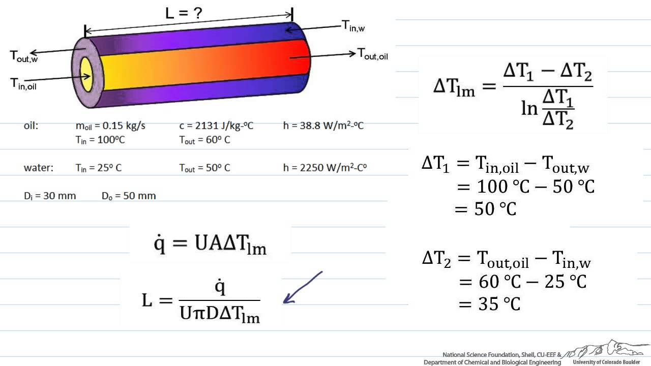
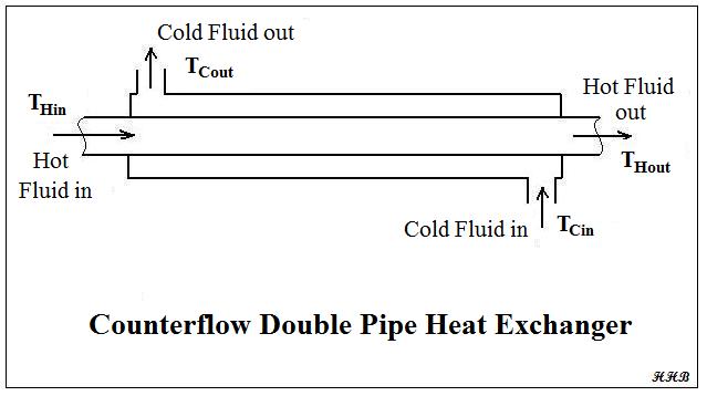
One fluid flow inside the small pipe and the other fluid moves by the annulus between the two pipes. U is the overall heat transfer coefficient in BTUhr-ft2-oF A is the heat transfer surface area in ft2 and ΔTlm is the log mean temperature difference in oF calculated from the inlet and outlet temperatures of both fluids. The pressure drop in pipes can be computed from the Darcy-Weisbach equation.
One fluid flows through the inner pipe tube side and the other flows through the annular space annulus. T1 T2 T1 T2 x The Simplest Heat Exchanger. The temperature difference between the fluid and the wall varies along the length of the heat exchanger.
610 under steady-state conditions d E d t 0 and as no shaft work is performed during pipe flow W ˆ s 0 the energy balance equation is. Use all data from your lab station across 5 lab sections Calculate and report overall heat transfer coefficient. For example Figure 3 illustrates.
Tion of the problem yields the optimum values of inner pipe. Therefore pressure drop Δ pp in the length L of the inner pipe is given by 15 Δ p p f p LG p 2 2 ρ p d where fp is the friction factor for the inner pipe. Q UA ΔTlm where.
The solution of the problem yields. 26 From Equation 1825 The total rate of heat transfer is therefore or 18. Dec 14 2021 This disclosure presents methods and systems.
The Basic Design Equation and Overall Heat Transfer Coefficient The basic heat exchanger equations applicable to shell and tube exchangers were developed in Chapter 1. The fundamental heat transfer relation q UAT 1. Prove steady state Measure appropriate temperatur es flow rates and replicates Share raw data with classmates.
HEAT EXCHANGER ARCHITECTURE The basic structure of a double pipe heat exchanger consists of twoconcentrictubesFigure1andisusuallycommercializedin a hairpin structure Figure 2. The entire heat transfer process takes place in the large tube. Optimization of the system cost is laborious.
Equation 1824 can be written as where This is the temperature distribution along the pipe. In this paper the optimal design of the exchanger has been formulated as a geometric programming with a single degree of difficulty. Hairpin Heat exchangers with Multitube Finned inner Tubes From Equations 74 75 78 79 and 710 the hydraulic diameter for the Reynolds number and the pressure drop is and the equivalent diameter based on heat transfer For a double-pipe heat exchanger of length L the unfinned bare and finned areas are respectively.

Double Pipe Heat Exchanger Parallel Flow Download Scientific Diagram

Parallel Flow In A Double Pipe Heat Exchanger Download Scientific Diagram

Parallel Flow In A Double Pipe Heat Exchanger Download Scientific Diagram
Double Pipe Heat Exchanger Design With Counterflow Or Parallel Flow Bright Hub Engineering
Configuration Of A Double Pipe Heat Exchanger The Inner Pipe Is The Download Scientific Diagram
Sizing A Heat Exchanger Counter Flow Youtube
Heat Exchanger Thermal Design Calculations Spreadsheetlow Cost Easy To Use Spreadsheets For Engineering Calculations Available At Engineering Excel Spreadsheets

Double Pipe Heat Exchanger Animation Heat Exchanger Animation Otosection
0 comments
Post a Comment